Advanced Parameters
When you run a Feasibility request and create a Task, you can define geometric constraints such as Grazing Angle, Polarization, and Target Azimuth Angle.
Because these settings directly affect task feasibility, image quality, and scheduling success, they should be used with care. We recommend applying them only if you consider yourself an advanced user of SAR data, have specific requirements and are familiar with their tradeoffs.
Grazing Angle
What is a grazing angle?
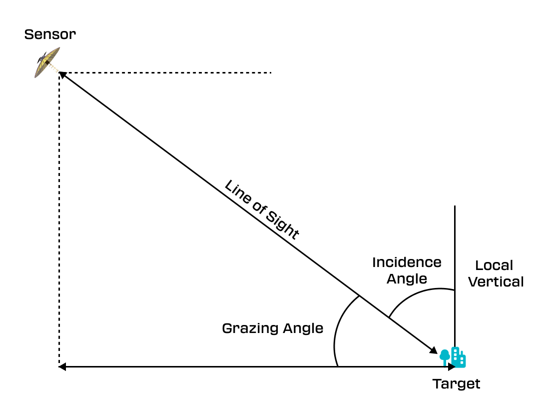
The grazing angle is formed between the radar's line of sight and the Earth's surface, precisely measured against a line parallel to the surface at the point where the radar beam contacts the Earth's surface. It's complemented by the incidence angle, which is defined by the angle between the radar's line of sight and the local vertical—a line perpendicular to the Earth's surface at the point of contact. Together, the grazing and incidence angles equal 90 degrees. The grazing angle plays a pivotal role in determining the radar's viewing angle, directly influencing the steepness or shallowness of the radar's approach.
How does grazing angle affect tasking?
This directly influences a collection's characteristics, such as contrast, and the ability to distinguish between different surface features. As a general rule, a higher grazing angle provides more image contrast but reduces the amount of access to the AOI. Conversely, lower grazing angles provide more access opportunities but may reduce the signal's return strength, making it harder to differentiate between objects or features on the ground.
Recommended Grazing Angles
Our recommended grazing angle ranges differ depending on your Imaging Mode and resolution.
Spotlight Mode: See Suggested Spotlight Parameters for recommended grazing angle ranges at different resolutions and multilook settings.
Scan Mode: See Suggested Scan Parameters for recommended grazing angle ranges based on resolution and scan length.
We suggest sticking with these defaults for most use cases. You can adjust them at your discretion, but be aware that overly restrictive grazing angle constraints may reduce feasibility and values outside our ranges can result in lower‑quality imagery.
How does the squint angle differ to grazing angle?
Unlike the grazing angle, which measures the steepness of the radar's observational approach vertically, squint introduces a horizontal angular component to the radar collection.
While you cannot directly set squint angles through our tasking parameters, you do have the ability to choose an access with a squint angle that falls within a preferred range from the opportunities available in your feasibility results. To ensure the best possible image quality, we keep accesses within an optimal squint range, avoiding the potential degradation that can occur with more extreme squint angles.
What does an AOI look like at different Grazing and Squint Angles?
Target Azimuth Angle
Target Azimuth is only applicable to Spotlight tasking.
What is target azimuth?
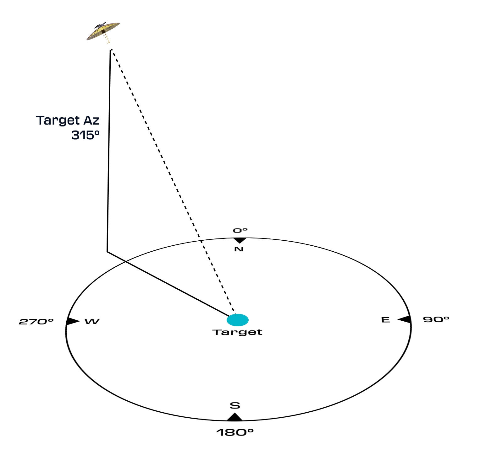
The target azimuth angle refers to the angle between true north and the line from the observer (in this case, the satellite) to the target, measured in a clockwise direction on the Earth's surface. It plays a crucial role in defining the orientation of the satellite relative to the target area. Unlike the grazing angle, which addresses the vertical interaction between the radar's line of sight and the Earth's surface, the target azimuth angle focuses on the horizontal alignment of the radar's observation path.
How does the target azimuth angle affect tasking?
Initially, we keep the target azimuth angle selection open, spanning the full range of 0-360 degrees. Direction of satellite may not impact your tasking use case and if it does, it is contingent on choosing one that complements the features in your scene. Otherwise, you may just have a preference of which direction your area of interest (AOI) is captured from.
When to adjust target azimuth
If you’re looking to capture a specific scene consider the features around it and utilizing a target azimuth angle that strategically allows for more direct illumination of your target area.
For example, if capturing a valley flanked by high mountains, a target azimuth that aligns with the length of the valley can be problematic. This can result in significant shadowing in the interior valley. One initial approach that might come to mind is to increase the grazing angle - this increases layover, but reduces shadows - however in this instance a far more effective method is to think about what direction provides the most open field of view when looking at your area of interest (the valley). By adjusting the satellite's orbit to pass at an angle more perpendicular to the valley's orientation, the radar beams could strike the valley sides more directly, illuminating previously shadowed areas and reducing the extent of shadowing in the SAR imagery.
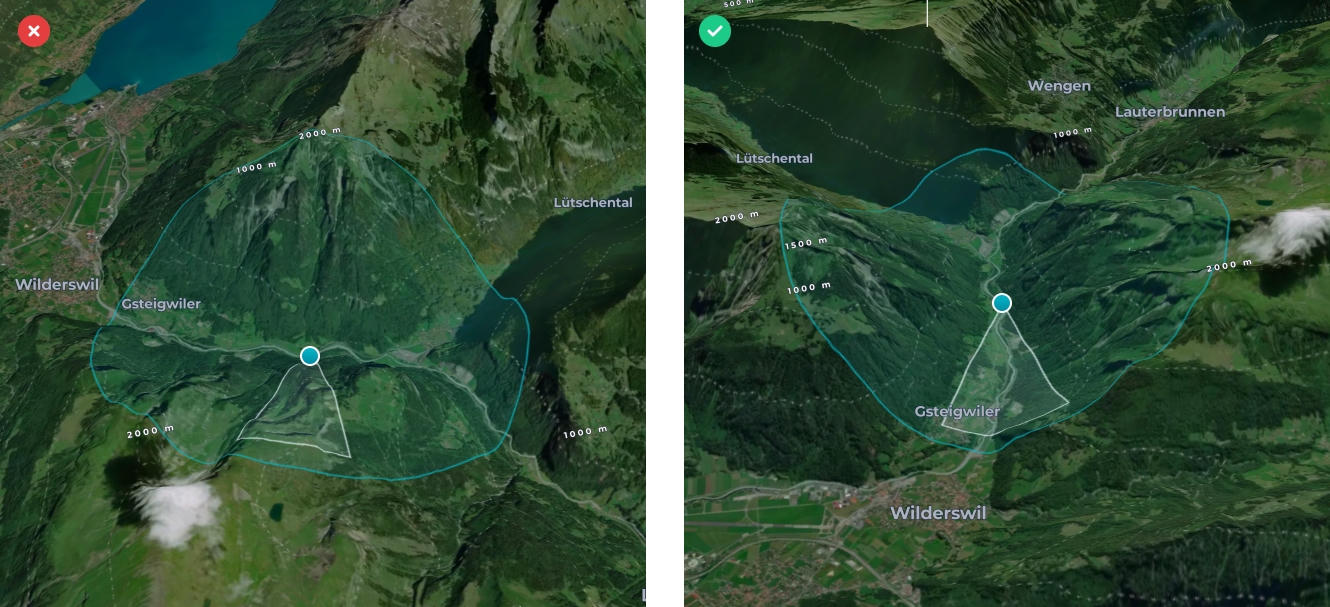
Target Azimuth facing mountain side (left), Target Azimuth has been set to view into the valley (right)
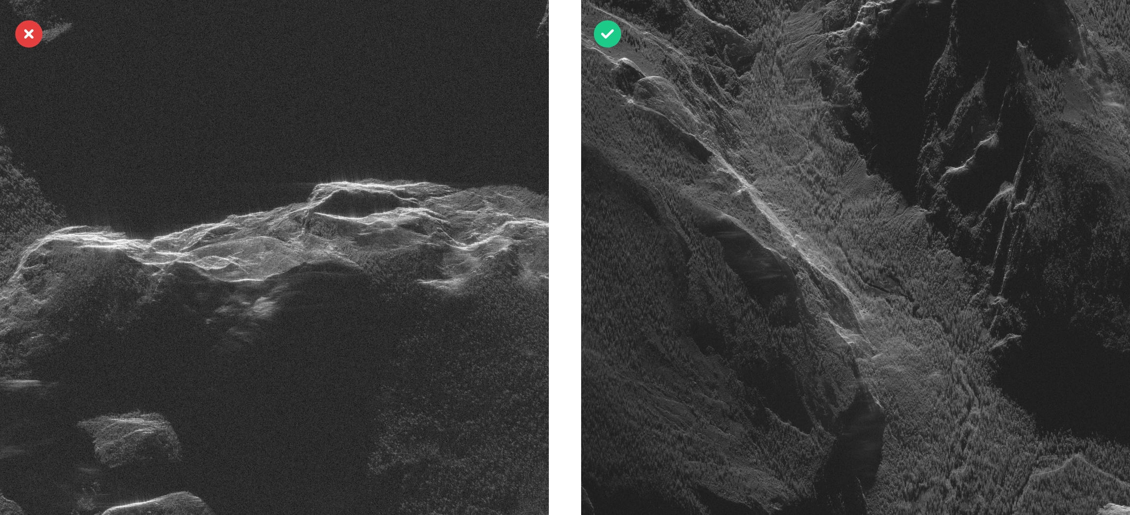
Approaching the target area (the valley) from between the mountain ranges provides great visibility (right) vs shadowing caused by facing mountain side (left)
Learn how distortions such as shadowing happen and how they can impact imagery. [Image Distortions]
Please note: The range of target azimuth angles available is constrained by the nature of our polar orbits. Due to the orbital path from north to south and vice versa, our satellite is unable to capture imagery directly ahead (in the travel direction) or directly behind (from the direction it came).
This limitation means that we cannot provide imaging looking directly towards the north or south.
Polarization
What is polarization?
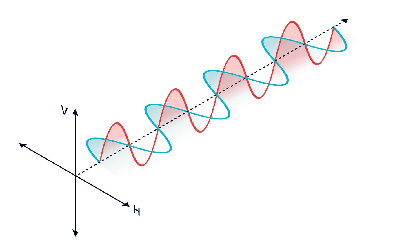
Polarization in SAR refers to the orientation of the radar wave as it interacts with the Earth's surface and is a crucial parameter for enhancing the interpretation of surface features. Our systems can transmit and receive signals horizontally (H) or vertically (V), leading to combinations like HH and VV where the first letter represents the transmission polarization and the second the reception. This capability allows for the collection of diverse data from the same area, offering insights into surface properties and variations.
How does polarization affect my collection?
Each polarization interacts differently with the Earth's surface, providing distinct insights into the area being imaged:
HH polarization, where the radar signal is transmitted and received horizontally, is suited to:
- Flood Mapping: Particularly useful for accurately delineating water extents, as it is less influenced by surface roughness caused by wind and waves.
- Vessel Detection: Good for identifying ships and other vessels on the water, as the metal structures typically reflect horizontal polarization strongly.
- Urban Infrastructure: Useful in detecting man-made structures, as horizontal surfaces like roads and buildings often reflect HH polarization well.
VV polarization, where the radar signal is transmitted and received vertically, is suited to:
- Oil Slicks: Preferred for spotting oil slicks on the ocean's surface, as oil-smoothed water reduces the backscatter in VV polarization, making slicks more visible.
- Ship wake detection: Preferred for detecting the wakes of ships as an indirect method of locating them, due to the wakes' visibility in VV imagery.
- Agricultural and Vegetation Monitoring: Helps in observing crop growth and characterizing vertical vegetation structure.
Polarization examples
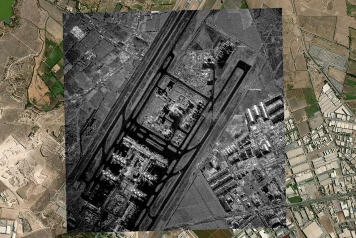
David Fuentes Airbase, Chile, HH 72.5° Grazing, 325.8° Target Azimuth
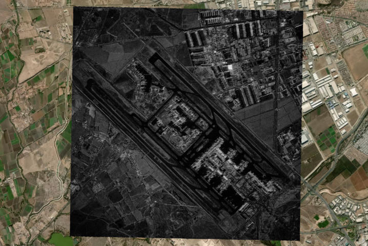
David Fuentes Airbase, Chile, VV 61.6° Grazing, 43.5° Target Azimuth
Updated 10 months ago